

Industry Overview
The insulated copper bus bar has become an essential component in contemporary electrical power distribution systems, offering superior conductivity, enhanced safety, and space-efficient design. According to market research, the global copper busbar market continues to expand steadily, driven by increasing demand from data centers, renewable energy installations, electric vehicle charging infrastructure, and industrial automation sectors.
Unlike bare conductors, an insulated copper bus bar incorporates a protective dielectric layer that prevents accidental contact, reduces the risk of short circuits, and allows for more compact installation in crowded electrical enclosures. The insulation system typically consists of materials such as PVC, heat-shrink tubing, or advanced epoxy coatings that provide reliable electrical isolation while maintaining thermal performance.
Manufacturing Process and Quality Standards
The production of high-quality insulated copper bus bar involves several precision manufacturing stages that directly impact performance and reliability.
Material Selection: High-conductivity copper with purity exceeding 99.9% is selected as the conductive core. Grades such as C11000 offer excellent electrical conductivity while providing enhanced mechanical strength for demanding applications.
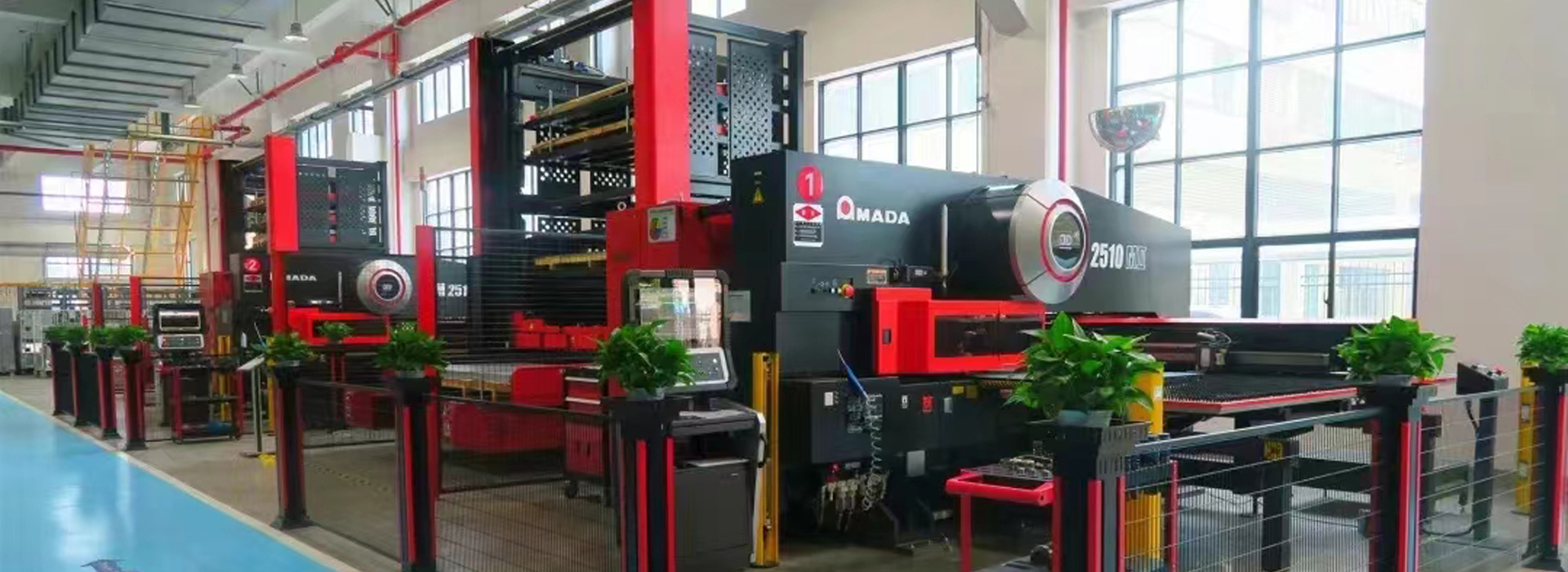
Precision Machining: The copper bar is cut and CNC machined to exact specifications, achieving tight tolerances of ±0.01 mm to ensure assembly accuracy. Punching operations for mounting holes must be performed using dedicated equipment, as improper cutting methods can compromise material integrity.
Surface Preparation: The conductor undergoes thorough cleaning and deburring to remove sharp edges and ensure uniform bonding with insulation materials. This step is critical for preventing stress points that could lead to insulation failure.
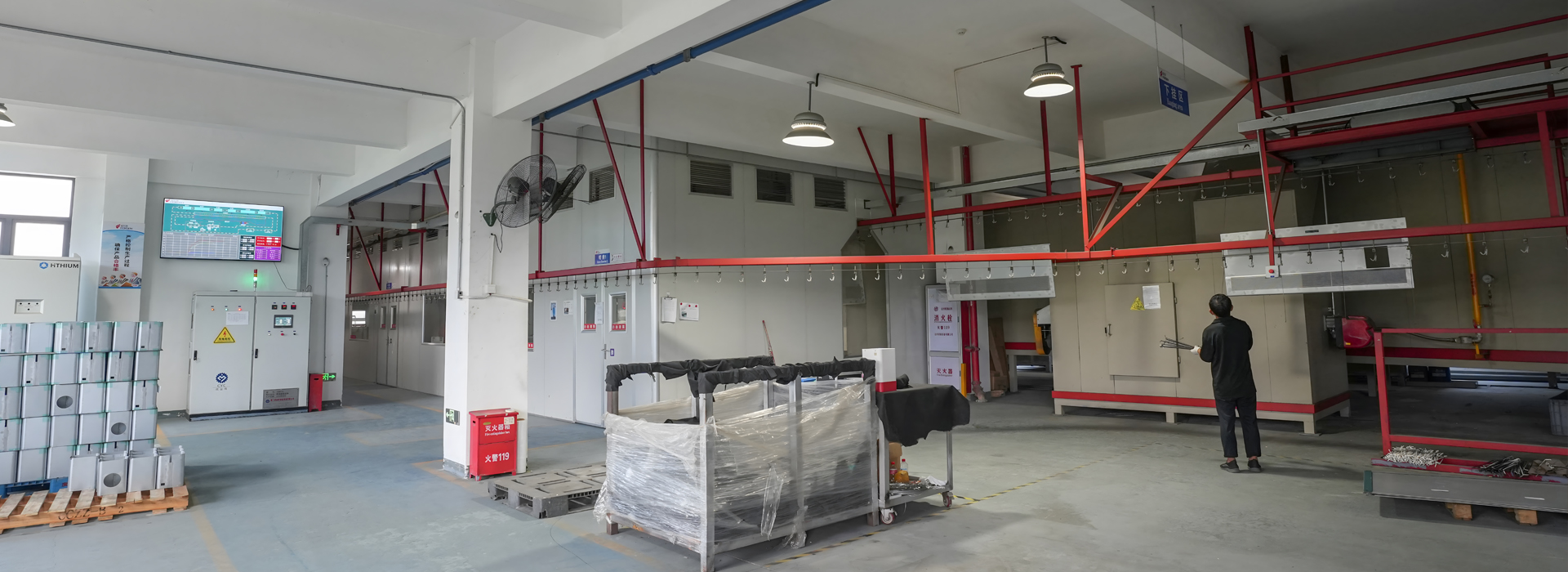
Insulation Application: The copper conductor is wrapped or coated with insulation material. Common methods include PVC extrusion, heat-shrink tubing application, or electrostatic epoxy powder coating followed by thermal curing.
Testing and Validation: Each insulated copper bus bar undergoes electrical insulation testing and dimensional inspection to guarantee safety and consistent performance. Dielectric strength testing typically requires withstanding 20 kV/mm or higher, depending on application voltage ratings.
Quality management systems certified to ISO 9001 ensure that manufacturing processes remain consistent and traceable. Compliance with international standards such as IEC 61439 for low-voltage switchgear assemblies is essential for global market acceptance.
Insulation Technologies and Material Properties
The insulation system of an insulated copper bus bar must balance multiple performance requirements including dielectric strength, thermal stability, mechanical durability, and environmental resistance.
PVC Insulation: Polyvinyl chloride offers cost-effective protection for indoor applications with moderate temperature requirements. It provides good chemical resistance and flame-retardant properties, typically achieving UL94 V-0 flammability rating.
Heat-Shrink Tubing: Radiation-crosslinked polyolefin materials provide tight, conformal coverage when heated, offering excellent mechanical protection and dielectric strength. This is particularly suitable for busbars with complex geometries or where field installation is required.
Epoxy Powder Coating: Electrostatic application followed by thermal curing creates a uniform, pinhole-free layer with exceptional adhesion. Epoxy coatings provide high dielectric strength and excellent environmental protection, making them ideal for outdoor or harsh industrial environments.
Polyester Film Wrapping: For space-constrained applications, thin polyester films deliver high dielectric strength while minimizing overall dimensions. This approach is common in switchgear and control panels where compact design is prioritized.
The selection of insulation material depends on operating voltage, temperature range, environmental exposure, and mechanical requirements. For example, busbars in outdoor renewable energy installations may require UV-stabilized epoxy coatings, while those in data center power distribution might prioritize thin polyester films for space efficiency.
Current Carrying Capacity and Thermal Management
The design of an insulated copper bus bar must account for thermal effects, as insulation can trap heat generated by current flow. Proper current rating selection is critical to prevent overheating and ensure long-term reliability.
Rating Principles: Current carrying capacity is determined by multiple factors including conductor cross-section, material grade, insulation type, installation method, and ambient temperature. Engineers must select busbars with capacity exceeding system requirements to maintain safe operating margins.
Temperature Rise Limits: Industry standards such as IEC 61439 specify maximum temperature rise limits for busbar connections—typically 70K above ambient for bare conductors and lower for insulated systems. Exceeding these limits accelerates insulation aging and increases failure risk.
Derating Factors: When multiple insulated copper bus bar runs are installed in parallel, mutual heating requires derating. For two parallel bars, total capacity is approximately 1.6 times the individual rating, meaning the combined capacity is less than the simple sum.
Thermal Simulation: Modern engineering workflows incorporate computational thermal analysis to predict temperature distribution under peak loads. This enables optimization of conductor geometry and insulation selection before physical prototyping.
Installation Requirements and Best Practices
Proper installation of insulated copper bus bar systems is essential for achieving rated performance and ensuring long-term reliability.
Mounting Specifications: Busbars must be installed with appropriate clearances from enclosure walls and other components. Small gaps should be maintained to accommodate thermal expansion during operation.
Connection Techniques: Overlap connections should use through-bolts with conductive paste applied to contact surfaces to improve conductivity and reduce resistance. Bolts must be tightened to specified torque values with flat and spring washers properly installed.
Phase Identification: For AC systems, phase colors should be applied to all visible surfaces of the busbar. However, areas near electrical connections should remain uncoated to maintain conductivity.
Bending and Forming: Cold bending using dedicated equipment is required—hot bending is prohibited as it alters material properties. The distance from the bending point to the nearest support should follow manufacturer recommendations.
Expansion Accommodation: Long busbar runs require expansion joints or sliding supports to accommodate thermal expansion and contraction. Fixed anchor points should be located in the middle of the run, allowing ends to move freely.
Applications Across Industries
Insulated copper bus bar systems serve critical functions across diverse sectors, each with unique performance requirements.
Data Centers: Modern data centers demand high-density power distribution with minimal space occupation. Insulated busbars enable compact busway systems that deliver reliable power to server racks while reducing heat generation compared to traditional cabling. Their modular design supports rapid reconfiguration as IT loads evolve.
Electric Vehicles and Charging Infrastructure: In EV battery packs, insulated busbars provide low-resistance interconnections between cells and modules, accommodating vibration and thermal cycling during operation. Charging stations rely on high-current busbars to manage power flows between grids, converters, and vehicle connectors.
Renewable Energy Systems: Solar farms and wind turbines utilize insulated busbars in combiner boxes, inverters, and battery storage systems. Their corrosion resistance and ability to handle fluctuating currents make them ideal for outdoor renewable installations exposed to weather extremes.
Industrial Manufacturing: Factory power distribution systems use busbars to deliver electricity to motor control centers, robotic work cells, and heavy machinery. The organized layout of insulated busbars simplifies wiring in complex plant environments and improves safety for maintenance personnel.
Switchgear and Control Panels: Within electrical enclosures, insulated busbars organize power distribution while reducing wiring complexity. Their compact arrangement improves airflow for cooling and simplifies maintenance access. For stainless steel enclosure applications, busbar systems must maintain proper electrical clearance while maximizing space utilization.
FAQ
Q: What is the difference between bare and insulated copper bus bars?
A: Bare copper bus bars require physical separation and clearance distances to prevent accidental contact and short circuits. An insulated copper bus bar incorporates a dielectric coating that allows more compact installation, reduces clearance requirements, and provides protection against contact—enhancing safety in crowded electrical enclosures.
Q: How do I select the correct current rating for my application?
A: Current rating selection must consider the maximum continuous load, ambient temperature, installation method, and number of parallel runs. Consult manufacturer ampacity tables and apply appropriate derating factors. For critical applications, consider engineering analysis including thermal simulation to verify performance under worst-case conditions.